

PART ONE
Introduction & Foreword
Recent advancements in edge AI hardware and software have opened up exciting possibilities for intelligent, compact systems that were unimaginable just a few years ago. Among these innovations, Axelera’s Metis devices stand out—delivering exceptional AI throughput in a small form factor and low power envelope, enabling use cases that were previously out of reach.
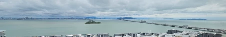
For the past few years, I’ve had the privilege of living by the sea, with a panoramic view of the vibrant marine activity unfolding daily. From cargo ships to fishing boats, leisure yachts to water scooters, the constant movement on the water has always fascinated me. As someone passionate about extracting insights from data, I’ve often wondered about the patterns and stories hidden in this daily marine traffic. Yet, as a human observer, I’m limited in how much I can monitor or record—leaving my curiosity largely unsatisfied.
Beyond curiosity, I’m deeply committed to the preservation of our marine ecosystems. Issues like overfishing, illegal activities, and violations of protected zones are real and pressing. Effective monitoring is essential to safeguard these resources and ensure sustainable use. These motivations led me to develop a marine monitoring and surveillance system—one that transcends human limitations and keeps watch over the sea 24/7, without blinking, sleeping, or getting distracted.


Main idea
The core idea behind my project was to build an edge-AI powered marine monitoring system that observes the stretch of sea visible from my balcony and logs all marine activity—ranging from small fishing boats to larger vessels. Simply recording video continuously would be impractical, storage-heavy, and offer little actionable insight. Instead, I envisioned a system that analyzes imagery in real-time, extracts and stores metadata, and allows for intelligent alerts based on activity type, location, and time.
To monitor marine traffic up to 10 km away (visibility permitting), I employed a long focal length “prime” lens. While this extended the range, it also narrowed the field of view—necessitating a “steering” mechanism to dynamically adjust the camera’s direction based on a higher-level monitoring plan. Use of direct-drive gimbal motors and Inertial Measurement Unit (IMU) feedback should enable “active” stabilization for future non-stationary use cases. This combination of edge AI, intelligent steering, and metadata-driven logging is what I set out to achieve in this project.
System Architecture
The Maritime Surveillance System is a comprehensive AI-powered platform designed for real-time maritime monitoring and security. Built on the RK3588 single-board computer with Axelera Metis M.2 AI accelerator, the system provides intelligent object detection, precise gimbal control, and automated restricted area monitoring with audio-visual alerts.
On a high level, the system has following main parts:
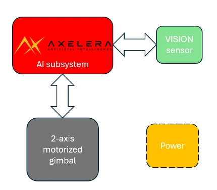
- The Axelera (Metis M.2) powered Rk3588 Single Board Computer (SBC) is the brains of the system and controls all the high-level planning and decision making.
- The vision sensor along with its optics is the “eyes” of the system.
- The 2 axis motorized gimbal subsystem which deals with all motion and positioning. It gets instructions from the SBC over UART interface.
- The power subsystem supplies everything with the right power.
Electronics Design
I have created a diagram of the full system showing how everything is connected in the system.
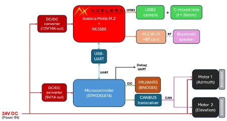
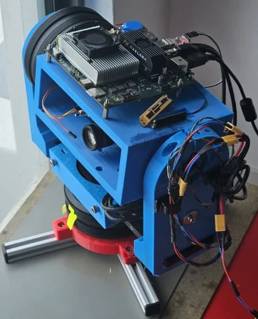
All the items map into the high-level diagram shared previously. The only connection between the brain part and the gimbal part is a UART connection. The gimbal implements its own control systems on the STM32G474 board and only gets high-level commands from the RK3588 SBC. The idea was that the whole gimbal should only need a 24V DC input power, and all other connections should be within the gimbal assembly. The M.2 Wi-Fi card is for internet and remote access, and Bluetooth is for giving audible alarms to an external speaker such as Amazon echo dot (provided with the kit).
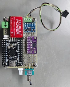
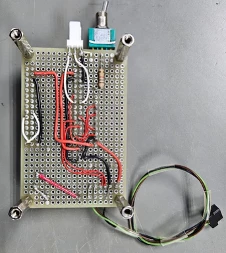
I combined the STM32G474 with the IMU (BNO08X), 3.3V CAN transceiver and a DC/DC power converter into one compact board.
One deviation in my current setup from the diagram above is that I couldn’t get the 12V/10A DC/DC converter delivered in time so currently I am running separate power to the Aetina RK3588 board (12V DC) and the motors/electronics (24V DC). Later I will switch to the single 24V DC input as planned.
Mechanical Design
I had been (on-and-off) working on building a 2 axis gimbal previously and was hoping to have something ready for the project by the time I received the hardware from Axelera. I even had some success with active stabilization algorithms. Pictured below is what I had at that point:
However, when I received the Aetina RK3588 board, I realized that the board was too big to fit on my existing inner-gimbal platform. This led to a domino effect of issues, and I ended up redesigning the whole gimbal from scratch. I had to redesign a much-bigger gimbal structure, which turned out to be a much bigger task than I had imagined. My home 3D printer is a 10-year-old Flashforge Dreamer with a limited print volume, so I had to divide my design into parts I could print easily.
Finally, after several days spent in SolidWorks, I had something workable:
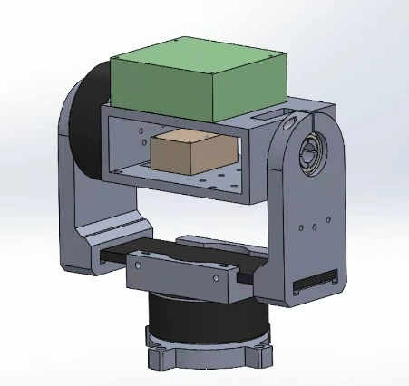
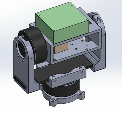
Since a gimbal needs a good amount of rigidity for any closed-loop control systems to function well, I designed the gimbal around a ~10mm thick aluminium plate (in black, above the yaw motor) I had lying around which served as a very rigid platform for the 3D printed parts. In hindsight, it turned out to be an excellent choice for a gimbal this size. The green box you see is a functional equivalent of the RK3588 base board (with Axelera Metis installed), with accurate hole placement and maximum sizes accounted for. The khaki box is an equivalent of the electronics board I was designing for it along with 4 x stand-offs. A careful design choice was to place the holes such that the IMU on the electronics board will fall on the pitch axis to avoid pitch movements coupling into accelerometers. The whole platform was design such that the top part could be shifted sideways after assembly to balance the gimbal in yaw axis (very important!).
The design took few days to print due to the (relatively large) size of the parts and (slow) speed of my printer. In fact, I suspected this and had started printing parts as I was finalizing them, from bottom to top.
I have made the design files available in the project github folder for anyone to replicate this or modify for their own setup.
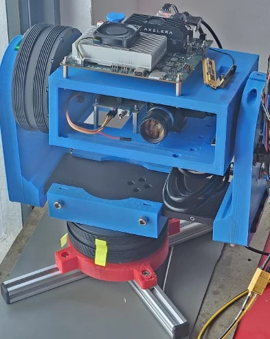
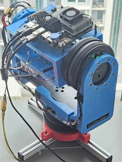
Final Assembly
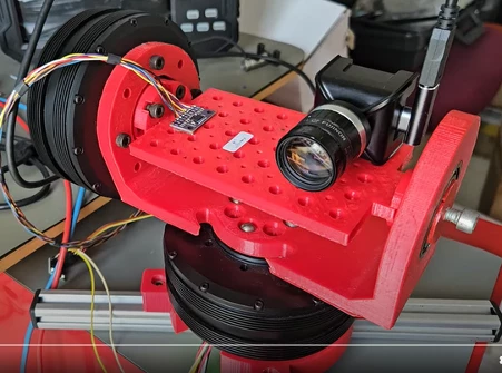
Eventually everything was assembled. The “proper” wiring alone took a day to make cables for all connections between electronics, motors, etc. Without further ado, here are some images of the final assembly:
The USB3 camera with 35mm C mount lens is clearly visible in this picture on right. On the left is the electronics board I built for the gimbal with the STM32G474, BNO08X IMU, CAN transceiver and DC/DC converter.
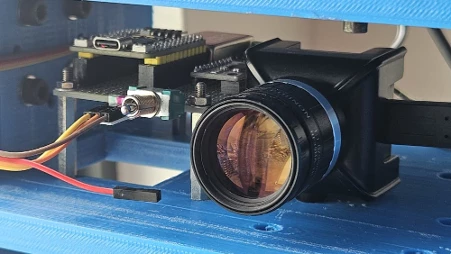
I used a 35mm lens retrofitted to a USB3 camera (See3CAM_CU30) via a M12-to-C-mount adapter. This was to get the desired detection distance needed.
The SBC with Axelera AI accelerator is mounted on top of the inner gimbal platform:
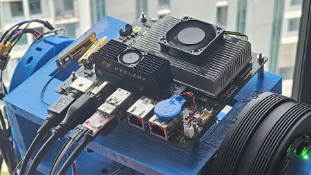
The reason for keeping the SBC on the inner gimbal platform is so that the high speed USB3 camera cables don’t have to pass through a slip ring (although I didn’t use slip rings in this version as my motors are not through-hole type.
Note: All design files are available at the project’s Github folder.
Continue to PART TWO of Sauron - Intelligent Marine surveillance system..